


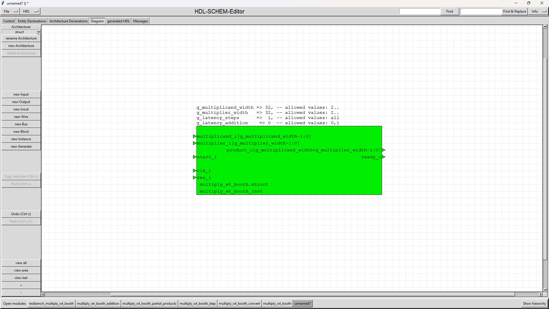
The VHDL 2008 module "multiply_wt_booth" (see symbol)
calculates the signed product of a multiplicand and a multiplier.
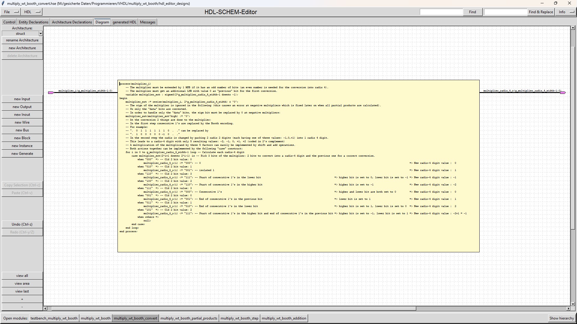
It uses Booth encoding for the multiplier. Booth encoding alone offers no advantage in a hardware implementation, if all
multiplications are to have the same latency. Instead there is a disadvantage, as the number of bits of the multiplier is increased by 1.
To overcome this disadvantage, the Booth encoded multiplier is converted into a radix-4 number with the values -2, -1, 0, +1, +2.
This radix-4 number has half as many digits as the original multiplier has bits.
These digits and the multiplicand can easily be multiplied together using shift and add operations.
The "multiply_wt_booth" module uses a Wallace tree to achieve a faster timing.
The advantage of using a Wallace tree is that partial products of the same weight are added in parallel rather than sequentially.
Furthermore, there is only a carry path in the final addition.
In contrary to the expectations the "multiply_wt_booth" module has not a better timing than the "multiply_wt" module (also available from this web site).
This can be seen, when both modules are configured in order to calculate the product in only 1 clock cycle.
The reasons are:
The "multiply_wt_booth" module must calculate the negated multiplicand (even if all operands are positive), which is not necessary in "multiply_wt".
In the "multiply_wt_booth" module each calculation of a partial product may have 5 different results, so a multiplexer is needed instead of an And-gate in "multiply_wt".
The reduced number of multiplier digits in the "multiply_wt_booth" module is not a big advantage as the Wallace tree in "multiply_wt" reduces the
number of terms to add in only 2 steps to the half (for example for a 32x32 multiplication 6 steps are needed in "multiply_wt_booth" instead of 8 in "multiply_wt").
Therefore the "multiply_wt_booth" module has a slightly worse timing than the "multiply_wt" module but still a better timing
than the modules "multiply", "multiply_cs", "multiply_sd" and "multiply_bsc" also available from this web site.
Be aware that the "multiply_wt_booth" module needs more design resources than "multiply_wt".
Note that if you are using an advanced synthesis tool such as Synopsys Design Compiler Ultra,
the "multiply_wt_booth" module design may not give a better timing than the other "multiply" designs.
Design Compiler Ultra already uses advanced arithmetic optimisations that implement fast addition structures.
The number of bits of multiplicand and multiplier are configured by generics.
Product, multiplicand and multiplier are numbers in 2's complement format.
The latency of the module can be configured by generics independently from the width of the operands.
This means, the module is configurable by generics in order
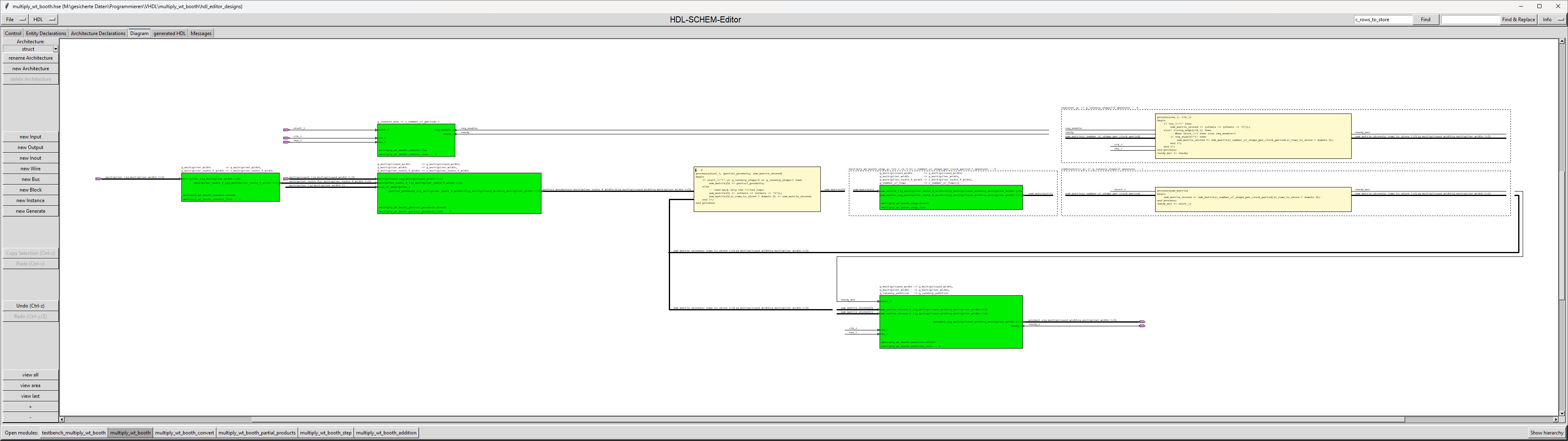
The "multiply_wt_booth" module was developed with HDL-SCHEM-Editor.
| Port name | Direction | Description |
|---|---|---|
| res_i | input | asynchronous reset input, 1-active Can be clamped to 0 when g_latency=0. |
| clk_i | input | clock input Can be clamped to 0 when g_latency=0. |
| start_i | input | This input expects an 1-active impulse of 1 clock cycle width in order to start the calculation. When g_latency=0 then back to back pulses can be used. |
| multiplicand_i(g_multiplicand_width-1:0) | input | Signed multiplicand (g_multiplicand_width is a generic). The input is latched at start=1 and can be changed afterwards. |
| multiplier_i(g_multiplier_width-1:0) | input | Signed multiplier (g_multiplier_width is a generic). The input is latched at start=1 and can be changed afterwards. |
| ready_o | output | 1-active impulse of 1 clock cycle width, when the calculation is ready (at latency 0 it gets active in the same clock cycle in which start_i gets active). |
| product_o(g_multiplicand_width+g_multiplier_width-1:0) | output | Signed product. Valid at ready_o=1. Only stable during calculation if g_latency_addition=1. |
| Generic name | Minimum Value | Maximum Value | Description |
|---|---|---|---|
| g_multiplicand_width | 2 | none | Number of bits of the multiplicand The first bit represents the sign as the operands have to be coded in 2's complement. |
| g_multiplier_width | 2 | none | Number of bits of the multiplier The first bit represents the sign as the operands have to be coded in 2's complement. |
| g_latency_steps | 0 | none | Latency of the Wallace tree calculations (processed by the "multiply_wt_booth_step" submodules) in clock cycles When g_latency_steps is set to 0, the Wallace tree (built from submodules "multiply_wt_booth_step") is a combinatorial design. |
| g_latency_addition | 0 | 1 | Latency of the submodule "multiply_wt_booth_addition" in clock cycles This module adds the last 2 rows created by the last step of the Wallace tree. When g_latency_addition is 0, then "multiply_wt_booth_addition" is a combinatorial design. |
The module "multiply_wt_booth" is a hierarchical module, which is built by 5 submodules.
| Submodule name | Functionality |
|---|---|
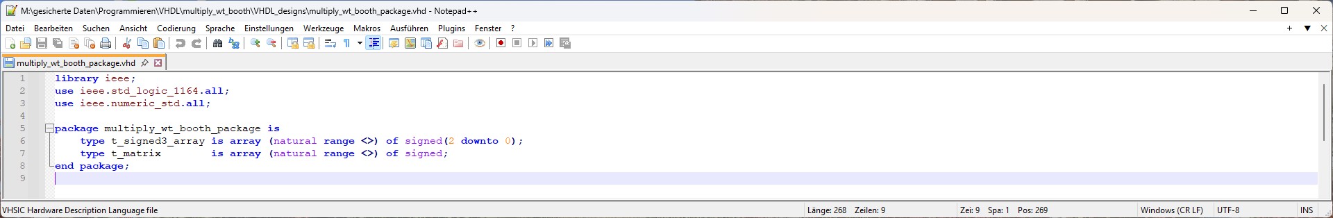
| multiply_wt_booth_package |
The package multiply_wt_booth_package contains a VHDL 2008 unconstrained array type definition for a matrix (array of "signed"). |
| multiply_wt_booth_convert |
The "multiply_wt_booth_convert" module converts the multiplier (coded in 2's complement) into a radix-4 number based on Booth encoding. The signbit of the multiplier is ignored during this conversion |
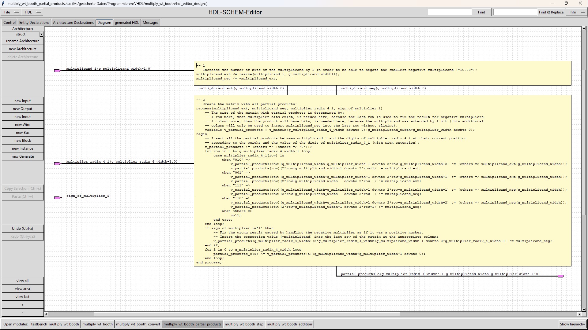
| multiply_wt_booth_partial_products |
The "multiply_wt_booth_partial_products" module multiplies the multiplicand with each radix-4 digit of the multiplier. The "multiply_wt_booth_partial_products" submodule is a combinatorial design, because it has a delay of only 1 multiplexer and inserting flipflops for all its outputs would insert a large number of flipflops (for example 1024 flipflops for a 32x32 multiplication). |
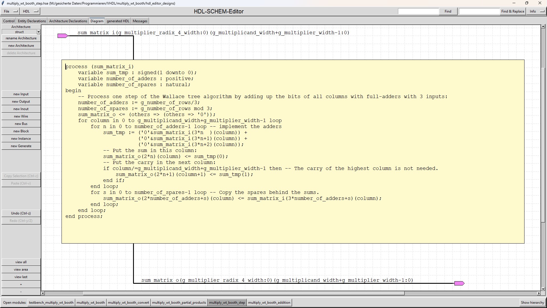
| multiply_wt_booth_step |
The "multiply_wt_booth_step" module processes 1 step of the Wallace tree algorithm. The submodule is instantiated as many times as Wallace tree steps are processed during a clock cycle (depending on the generic g_latency_steps).
The "multiply_wt_booth_step" submodule has a generic named g_number_of_rows. This generic determines how many rows of
the incoming Wallace tree matrix are relevant in this step. This reduces the number of adders which are inserted
in each step, so that the "multiply_wt_booth_step" submodules all differ (when using a modern synthesis tool this reduction
would also be achieved by automatically removing all adders whose inputs are tied to 0). |
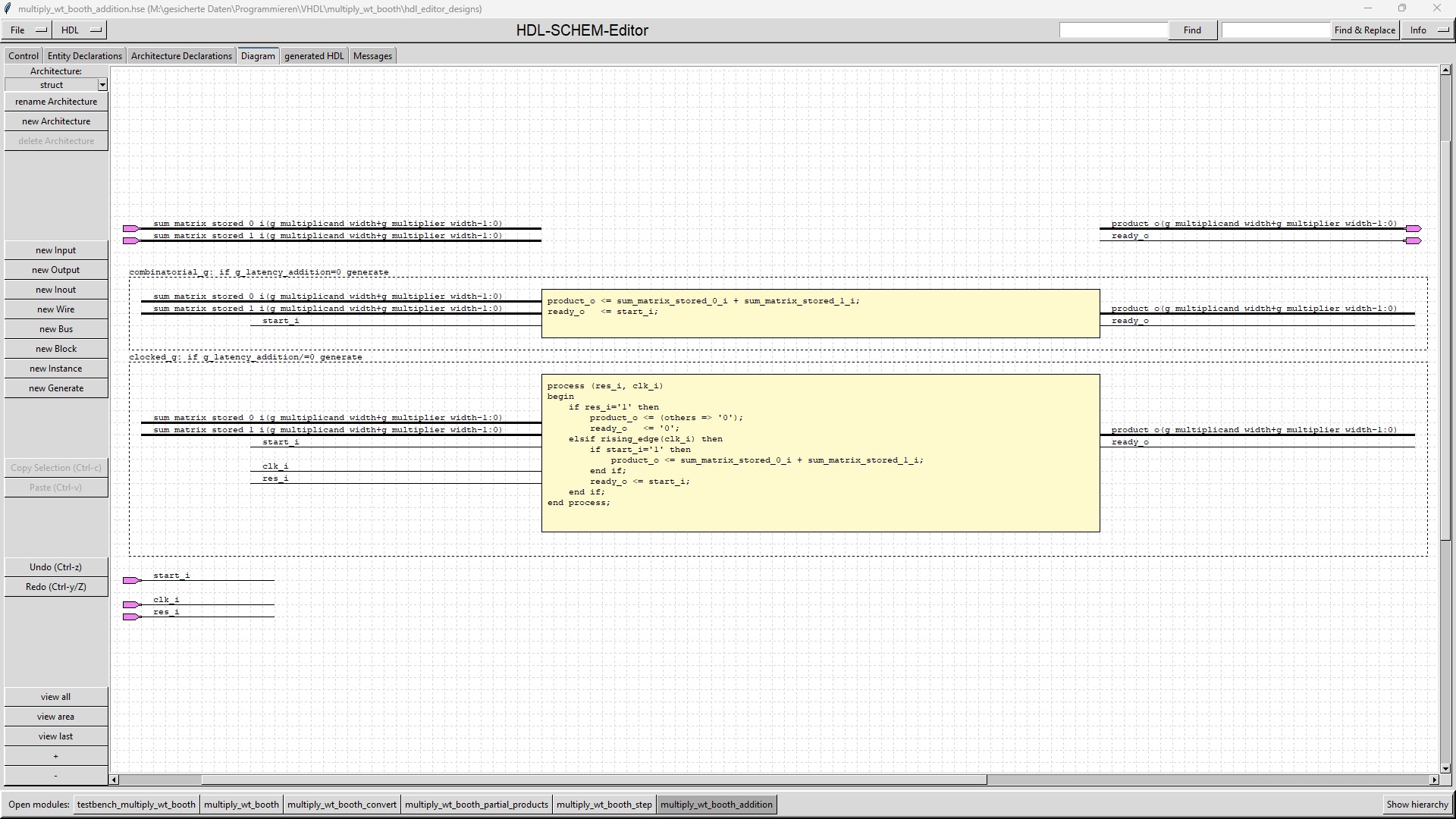
| multiply_wt_booth_addition |
The "multiply_wt_booth_addition" adds the last remaining 2 rows of the Wallace tree by a normal adder. If g_latency_addition=0 then the "multiply_wt_booth_addition" submodule is a combinatorial design. Otherwise the "multiply_wt_booth_addition" submodule will use a register to store the sum, in order to relax the timing at the product_o output. |
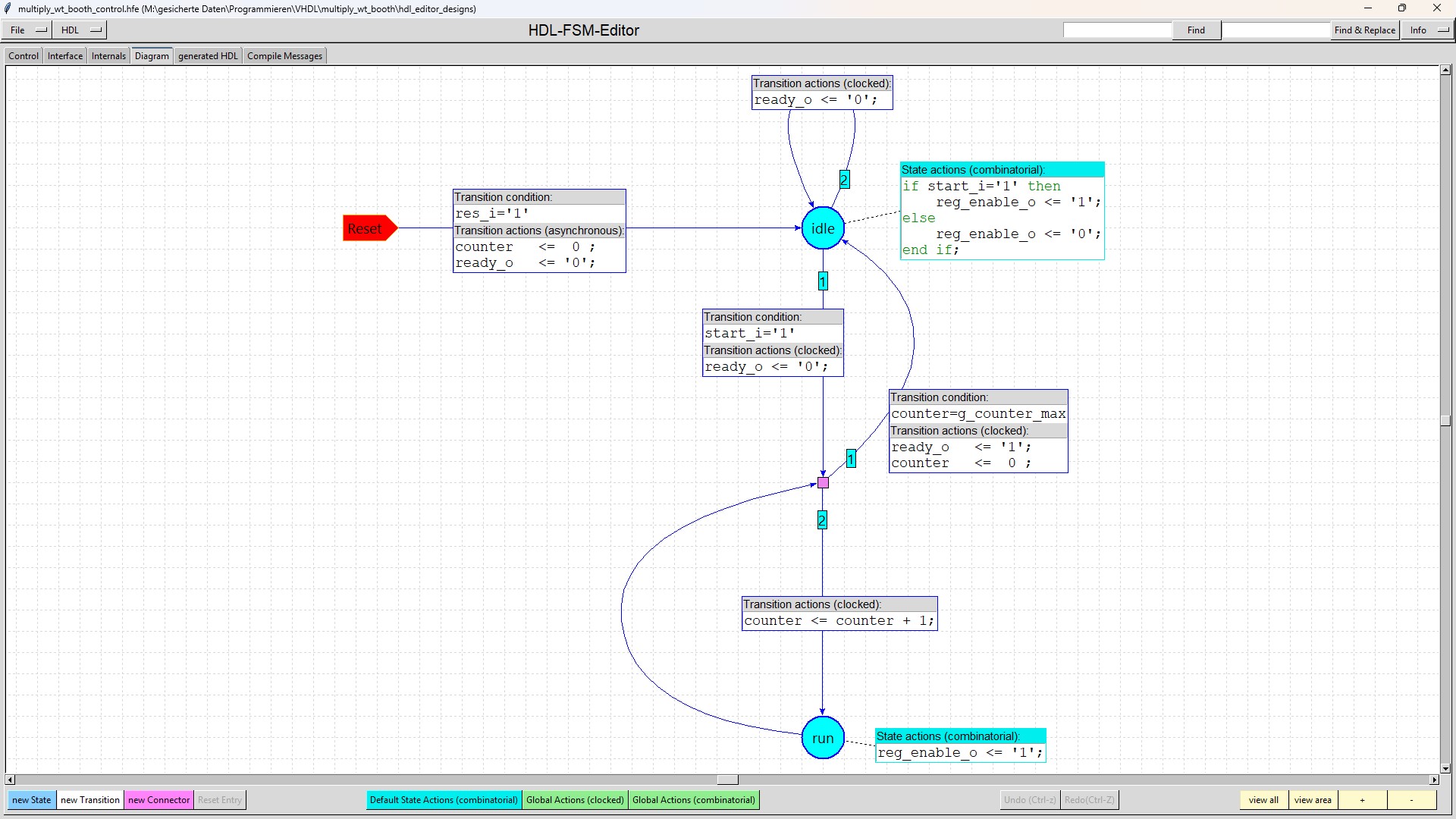
| multiply_wt_booth_control |
The multiply_wt_booth_control modules generates all the control signals which are needed. |
There are no limitations for the generics g_multiplicand_width and g_multiplier_width (except that they must be bigger than 1).
These generics are most of the time determined by the environment, where the module multiply_wt_booth is used.
The generic g_latency_addition is used to relax the timing and to adapt the module to the requirements of its environment.
If the value is different from 0, a register is inserted at its outputs to break the timing paths.
There is no limitation for the generic g_latency_steps. But this generic determines not only the latency but also how
difficult it will be to reach timing closure: The smaller the value is chosen, the harder it will be to reach timing closure.
As the "multiply_wt_booth" module is built to provide a fast multiplication, setting g_latency_steps to 0 or 1 makes the most sense.
If g_latency_steps is equal to 0, then a completely combinatorial Wallace tree is built.
In this case as many "multiply_wt_booth_step" submodules are instantiated as are needed to reduce the Wallace tree matrix to 2 rows.
If g_latency_addition is also set to 0, then the complete module multiply_wt_booth is a combinatorial design.
If g_latency_steps is equal to 1, then a register is added after the Wallace tree matrix is reduced to 2 rows.
The number of instantiated "multiply_wt_booth_step" submodules is the same as in the case g_latency_steps=0.
If the value of g_latency_steps is greater than 1, fewer "multiply_wt_booth_step" submodules are instantiated.
In this case after the first clock cycle the Wallace tree matrix is only reduced to a number of rows which
is bigger than 2. These rows are then stored in a register and fed back into the first "multiply_wt_booth_step" submodule.
This "feed back" process is repeated until the Wallace tree matrix is reduced to 2 rows.
During each iteration of the feedback loop, there are more adders available in the 'multiply_wt_booth_step' submodules
than are needed. However, this is irrelevant because the unnecessary adders are all fed with zeros.
If the value of g_latency_steps is greater than 1 and the number of steps needed for reducing the Wallace tree
matrix to 2 rows is not an integer multiple of g_latency_steps, then more than the needed steps are processed.
In this case, the second row of the Wallace tree matrix is gradually emptied, meaning that it may even end up
filled with only zeros.
Source code for HDL-SCHEM-Editor and HDL-FSM-Editor for "multiply_wt_booth" module and its testbench (Number of downloads =
375 ).
With these files the schematics and the state-diagram of "multiply_wt_booth" module can be loaded into HDL-SCHEM-Editor or
HDL-FSM-Editor and can be easily read and modified:
All module VHDL-files of the "multiply_wt_booth" module (Number of downloads =
393 ).
These files were generated by HDL-SCHEM-Editor and HDL-FSM-Editor:
All testbench VHDL-files of the "multiply_wt_booth" module (Number of downloads =
381 ).
These files were generated by HDL-SCHEM-Editor and HDL-FSM-Editor:
You should extract all archives into a folder named "multiply_wt_booth".
Then you should load the toplevel (probably the testbench) into HDL-SCHEM-Editor.
When you navigate through the design hierarchy by a double click at each symbol,
HDL-SCHEM-Editor will find the submodules on your disk and ask if it can replace
the original path to the submodule by the new one at your disk.
After storing the changed modules the relocation of the source files is done
(instead you could replace "M:/gesicherte Daten/Programmieren/VHDL/multiply_wt_booth" in all
"hdl_editor_designs/*.hse" source files by your path to this directory with your editor).
Now you can navigate through the design by HDL-SCHEM-Editor and generate HDL by HDL-SCHEM-Editor
for all modules except multiply_wt_booth_control, for which the HDL must be generated by HDL-FSM-Editor.
Of course there is only need for generating HDL, if you change something at the modules,
because you can find the HDL in VHDL_designs.zip and VHDL_testbenches.zip.
If you want to simulate or modify the modules by HDL-SCHEM-Editor you also must adapt the information in the
Control-tab of the toplevel you want to work on. There you must define a "Compile through hierarchy command",
an "Edit command", the path to your HDL-FSM-Editor and a "Working directory".
Version 1.0 (16.07.2025):
If you detect any bugs or have any questions,
please send a mail to "matthias.schweikart@gmx.de".