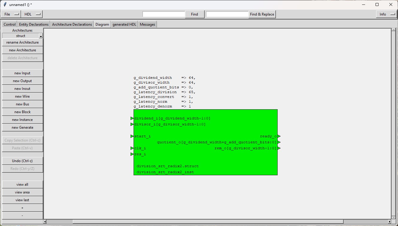


The module "division_srt_radix2" (see symbol)
calculates the signed quotient and the signed remainder of an integer dividend and an integer divisor.
The calculation is performed without converting the dividend and the divisor into unsigned numbers.
But both operands are normalised prior to the start of the division operation.
So as the module "division", the module "division_srt_radix2" must complete an additional step before the division can be executed.
But in contrary to the "division" module no additional data bit is introduced by the normalization.
The "division" and the "division_signed" module determines a quotient bit by calculating all bits of an intermediate result.
The "division_srt_radix2" module, on the other hand, only calculates the 4 most significant bits of an intermediate result and
then "guesses" the quotient bit with the help of a small additional logic. Due to this additional logic, "division_srt_radix2" only
achieves better timing when the operands are wider than about 32 bits. This limit is of course technology-dependent and
must be determined experimentally.
The term "radix2" means that each quotient-bit must be multiplied with 2**-i (i= bitposition) to get
its contribution to the overall normalized quotient (there exist other SRT divisions with radix 4, 16, ...).
The number of bits of dividend and divisor are configured by generics.
Dividend, divisor, quotient and remainder are numbers in 2's complement format.
The quotient is first not calculated as a binary number but as a number with bit values +1, 0 or -1.
After the division the quotient is converted into a 2's complement number.
Both quotient and remainder are fixed in some cases.
The latency of the module can be configured by generics independently from the width of the operands.
This means, the module is configurable by generics in order
The module "division_srt_radix2" was developed with HDL-SCHEM-Editor.
| Port name | Direction | Description |
|---|---|---|
| res_i | input | asynchronous reset input, 1-active Can be clamped to 0 when all latency generics have the value 0. |
| clk_i | input | clock input Can be clamped to 0 when all latency generics have the value 0. |
| start_i | input | This input expects an 1-active impulse of 1 clock cycle width in order to start the calculation. When all latency generics have the value 0 then back to back pulses can be used. |
| dividend_i(g_dividend_width-1:0) | input | Signed dividend (g_dividend_width is a generic). The input is latched at start=1 when g_latency_norm is different from 0. Otherwise it must kept stable during the operation. |
| divisor_i(g_divisor_width-1:0) | input | Signed divisor (g_divisor_width is a generic). The input is latched at start=1 when g_latency_norm is different from 0. Otherwise it must kept stable during the operation. |
| ready_o | output | 1-active impulse of 1 clock cycle width, when the calculation is ready (When all latency generics have the value 0 it gets active in the same clock cycle in which start_i gets active). |
| quotient_o(g_dividend_width+g_add_quotient_bits:0) | output | Signed quotient. Valid at ready_o=1 until the next start of a calculation or until the end of the next calculation if g_latency_convert or g_latency_denorm is different from 0. |
| rem_o(g_divisor_width-1:0) | output | Signed remainder. Valid at ready_o=1 until the next start of a calculation or until the end of the next calculation if g_latency_convert or g_latency_denorm is different from 0. |
| Generic name | Minimum Value | Maximum Value | Description |
|---|---|---|---|
| g_dividend_width | 5 | none | Number of bits of the dividend The first bit represents the sign as the operands have to be coded in 2's complement. |
| g_divisor_width | 3 | none | Number of bits of the divisor The first bit represents the sign as the operands have to be coded in 2's complement. |
| g_add_quotient_bits | 0 | none | If this generic is different from 0, then additional quotient bits below the binary point for integer are calculated. |
| g_latency_norm | 0 | 1 | Latency (in clock cycles) of the sub-module division_srt_radix2_norm which normalizes dividend_i and divisor_i. When g_latency_norm is 0, then the sub-module is a combinatorial design. Bigger values than 1 are handled as 1. |
| g_latency_division | 0 | none | Latency of the division (in clock cycles) When g_latency_division is 0, then the division is implemented as a combinatorial design. |
| g_latency_convert | 0 | 1 | Latency (in clock cycles) of the sub-module division_srt_radix2_convert which converts quotient and remainder into binary format. When g_latency_convert is 0, then the sub-module is a combinatorial design. Bigger values than 1 are handled as 1. |
| g_latency_denorm | 0 | 1 | Latency (in clock cycles) of the sub-module division_srt_radix2_denorm and the sub-module division_srt_radix2_denorm_remainder which calculate the not normalized results. When g_latency_convert is 0, then the sub-module is a combinatorial design. Bigger values than 1 are handled as 1. |
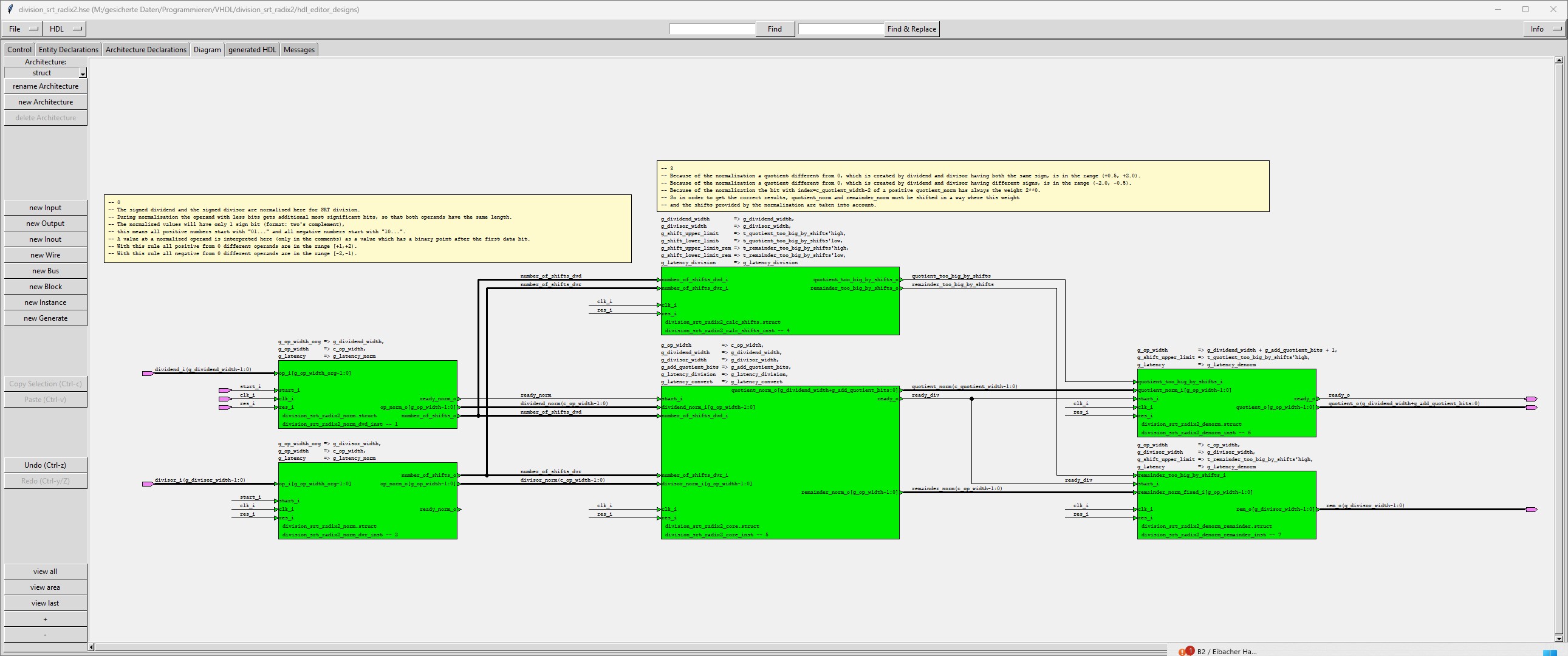
The module "division_srt_radix2" is a hierarchical module, which is built by these submodules:
| Submodule name | Functionality |
|---|---|
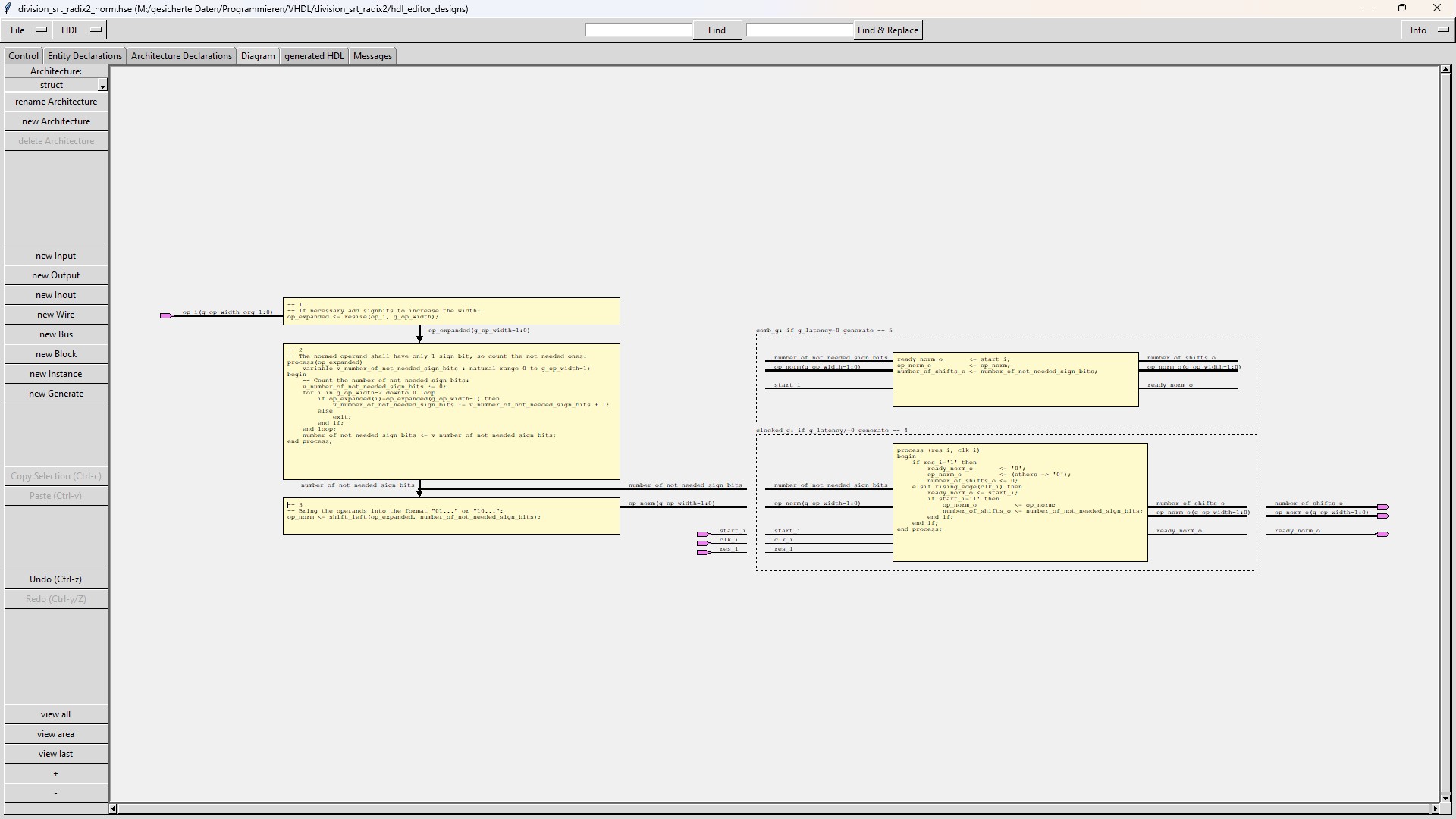
| division_srt_radix2_norm |
The sub-module "division_srt_radix2_norm" normalizes the dividend and the divisor.
In a first step the sub-module resizes the operand from the original number of bits given by the generic g_op_width_org to |
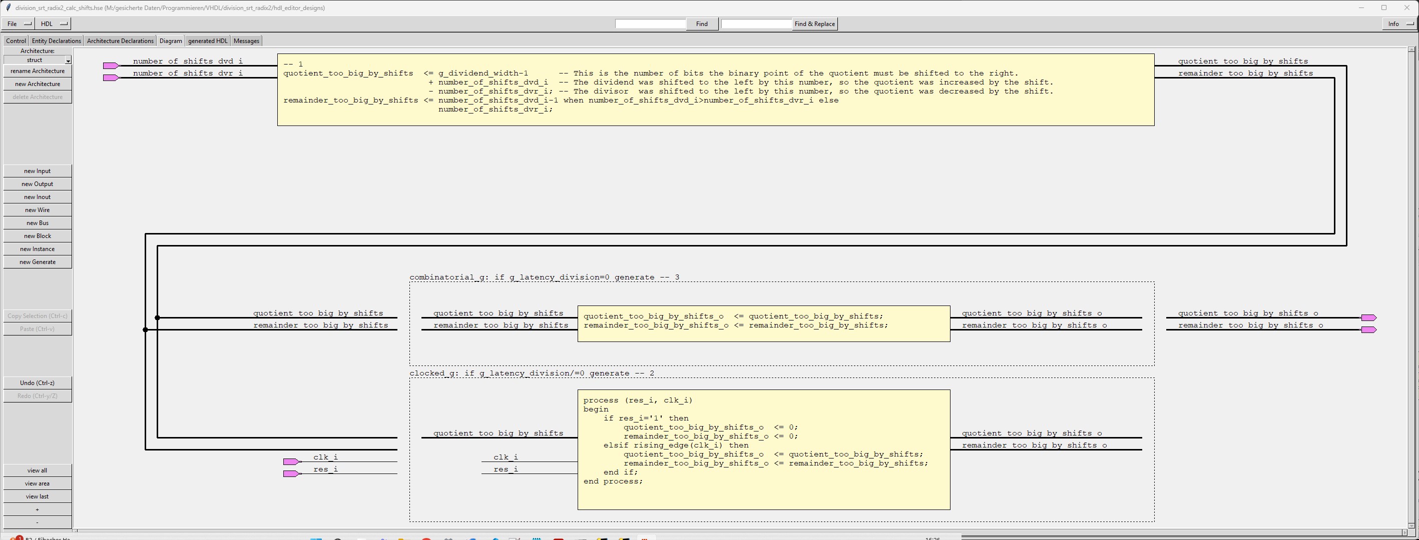
| division_srt_radix2_calc_shifts |
The sub-module "division_srt_radix2_calc_shifts" calculates the number of shifts for the de-normalization of quotient and remainder. When the generic g_latency_division is different from 0, then the calculated numbers are both stored in a register. |
| division_srt_radix2_denorm |
The sub-module "division_srt_radix2_denorm" de-normalizes the quotient based on the shift-numbers calculated by "division_srt_radix2_calc_shifts" When the generic g_latency_denorm is different from 0, then the result is stored in a register. |
| division_srt_radix2_denorm_remainder |
The sub-module "division_srt_radix2_denorm_remainder" de-normalizes the remainder based on the shift-numbers calculated by "division_srt_radix2_calc_shifts" When the generic g_latency_denorm is different from 0, then the result is stored in a register. |
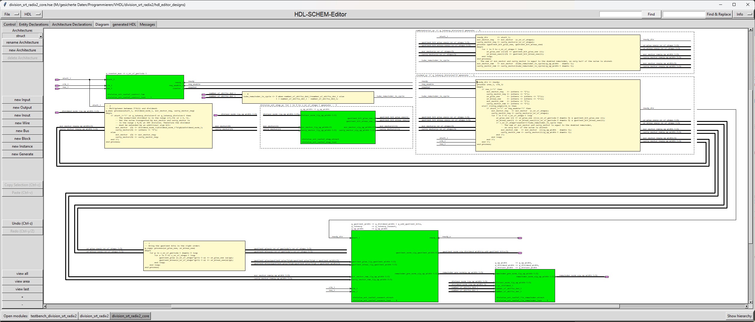
| division_srt_radix2_core |
The division_srt_radix2_core calculates the normalized quotient and the normalized remainder.
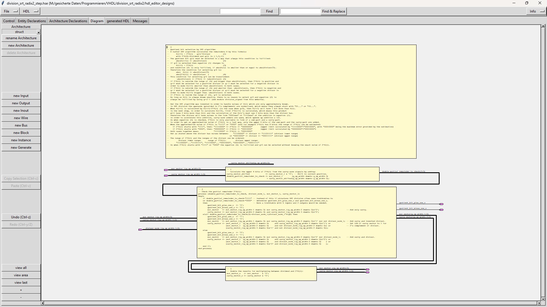
The module "division_srt_radix2_core" uses the sub-module "division_srt_radix2_step" which performs 1 step of the algorithm and
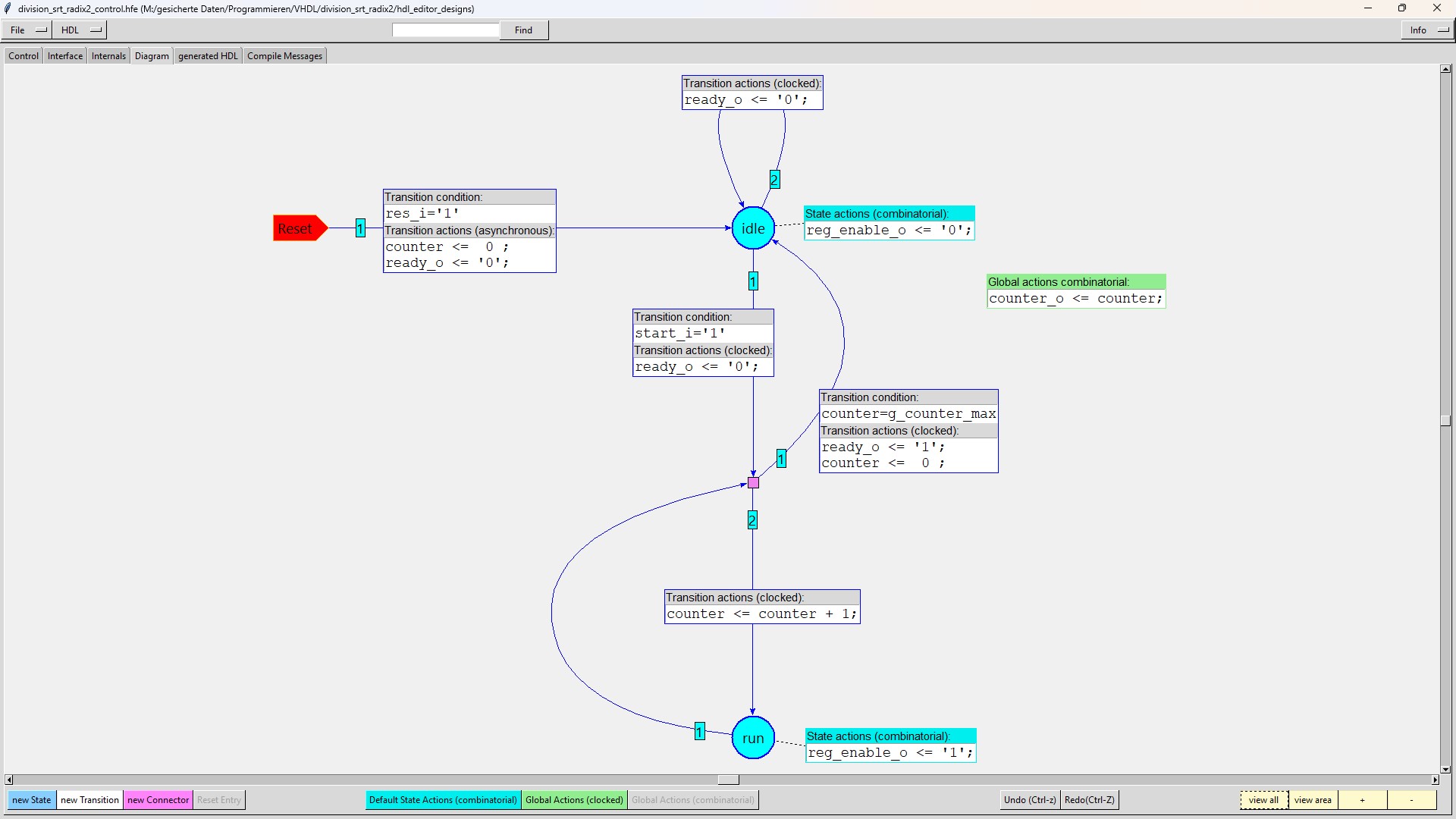
The module "division_srt_radix2_core" uses the sub-module "division_srt_radix2_control" which enables registers and
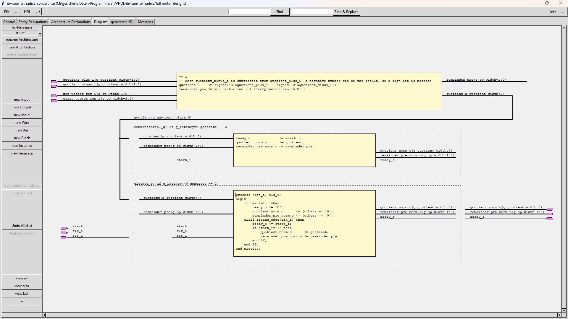
The module "division_srt_radix2_core" uses the sub-module "division_srt_radix2_convert" which converts the redundant number format
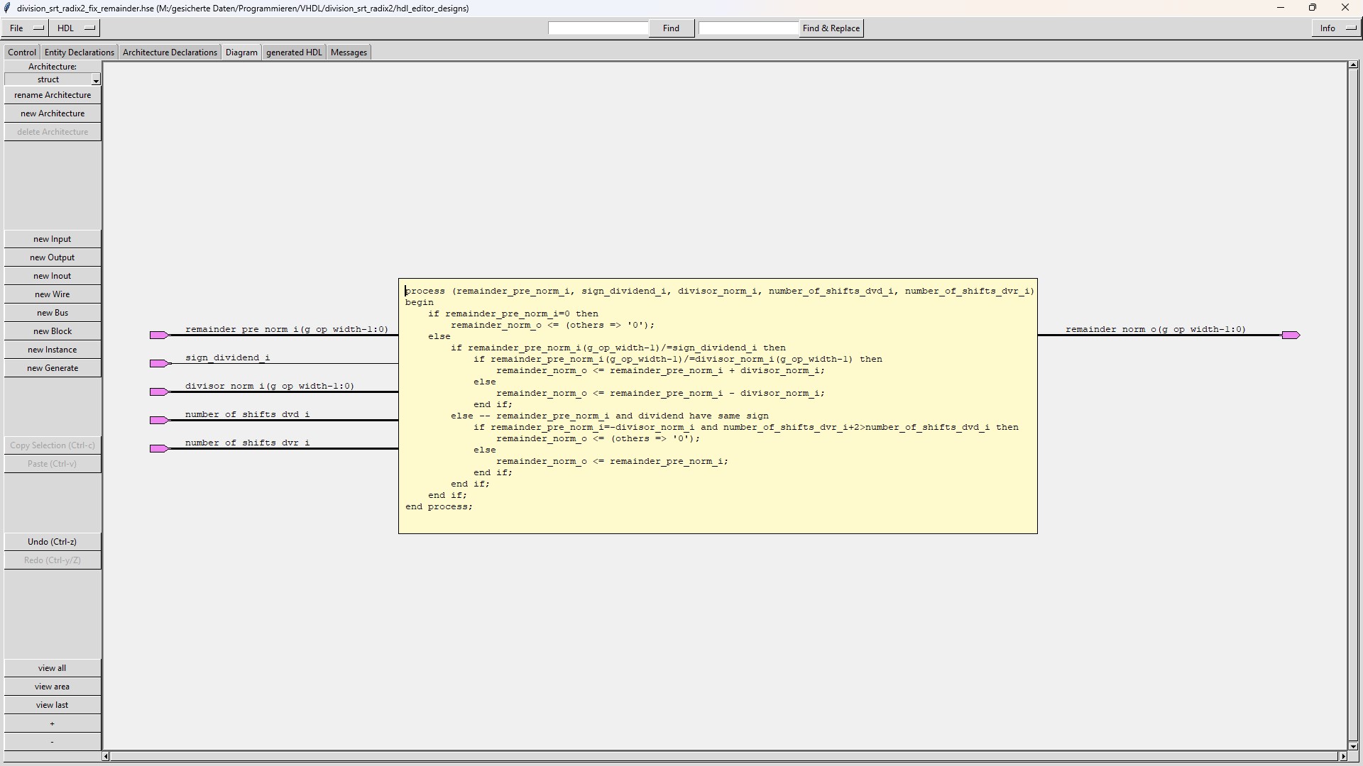
The module "division_srt_radix2_core" uses the sub-module "division_srt_radix2_fix_remainder" which fixes the remainder when it has |
| division_srt_radix2_control |
The "division_srt_radix2_control" module enables the shift registers in which the quotient bits are stored (in redundant number format). |
| division_srt_radix2_step |
The "division_srt_radix2_step" module calculates the 4 most significant bits of the intermediate result from the carry-save signals. |
| division_srt_radix2_convert |
The "division_srt_radix2_convert" module converts the quotient with bit-values -1, 0 or +1 into a 2's complement number. |
| division_srt_radix2_fix_remainder |
The sub-module "division_srt_radix2_fix_remainder" fixes the remainder when it has the wrong sign or when it is equal to the negated divisor. |
There are no limitations for the generics g_dividend_width and g_divisor_width (except that they cannot be smaller than their minimum value).
These generics are most of the time determined by the environment, where the module division_srt_radix2 is used.
When the generic g_add_quotient_bits is different from 0, more steps of the division algorithm have to be executed,
which causes more hardware effort and longer calculation time.
There is also no limitation for the generic g_latency_division, but the smaller the value is chosen,
the harder it will get to reach timing closure.
The optimal value for g_latency_division can be calculated in this way:
The number of quotient bits which are calculated is given by the sum g_dividend_width+1+g_add_quotient_bits (the
"+1" in this sum is caused by a division when the smallest negative number is divided by -1, because then
an additional bit is needed to present the quotient in 2's complement).
So when g_latency_division=g_dividend_width+1+g_add_quotient_bits then 1 bit of of the quotient is calculated
in 1 clock cycle, which is the optimal value for reaching time closure.
If g_latency_division is bigger than g_dividend_width+1+g_add_quotient_bits, then also 1 bit of the quotient is
calculated in each clock cycle, but the additional quotient bits are not connected to the output.
If g_latency_division is smaller than g_dividend_width+1+g_add_quotient_bits, then more than 1 bit of the quotient
must be calculated in 1 clock cycle. This makes reaching timing closure more difficult.
Setting g_latency_norm different from 0, increases the overall latency by 1 clock cycle but makes reaching timing closure easier.
Setting g_latency_convert different from 0, increases the overall latency by 1 clock cycle but makes reaching timing closure easier.
Setting g_latency_denorm different from 0, increases the overall latency by 1 clock cycle but makes reaching timing closure easier.


Source code for HDL-SCHEM-Editor and HDL-FSM-Editor of the VHDL-module "division_srt_radix2" and its testbench (Number of downloads =
306 ).
With these files the schematics and the state-diagram of module division_srt_radix2 can be loaded into HDL-SCHEM-Editor or
HDL-FSM-Editor and can easily be read and modified:
All module VHDL-files of the module "division_srt_radix2" (Number of downloads =
361 ).
These files were generated by HDL-SCHEM-Editor and HDL-FSM-Editor:
All testbench VHDL-files of the testbench of the module "division_srt_radix2" (Number of downloads =
321 ).
These files were generated by HDL-SCHEM-Editor and HDL-FSM-Editor:
You should extract all archives into a folder named "division_srt_radix2".
Then you should load the toplevel (probably the testbench) into HDL-SCHEM-Editor.
When you navigate through the design hierarchy by a double click at each symbol,
HDL-SCHEM-Editor will find the submodules on your disk and ask if it can replace
the original path to the submodule by the new one at your disk.
After storing the changed modules the relocation of the source files is ready
(instead you could replace "M:/gesicherte Daten/Programmieren/VHDL/division_srt_radix2" in all
"hdl_editor_designs/*.hse" source files by your path to this directory with your editor).
Now you can navigate through the design by HDL-SCHEM-Editor and generate HDL by HDL-SCHEM-Editor for
all modules except division_srt_radix2_control, for which the HDL must be generated by HDL-FSM-Editor.
Of course there is only need for generating HDL, if you change something at the modules, because you can find the HDL in VHDL_designs.zip and VHDL_testbenches.zip.
If you want to simulate or modify the modules by HDL-SCHEM-Editor you also must adapt the information in the Control-tab of the toplevel you want to work on.
There you must define a "Compile through hierarchy command", an "Edit command", the path to your HDL-FSM-Editor and a "Working directory".
Version 1.2 (18.10.2024):
Version 1.1 (29.09.2024):
Version 1.0 (11.09.2024):
If you detect any bugs or have any questions,
please send a mail to "matthias.schweikart@gmx.de".